Twin dio possible?
Moderator: Moderator
-
Majourlittle
- Elite

- Posts: 314
- Joined: Thu Feb 24, 2011 11:09 am
- Location: Broken Arrow, OK
Re: Twin dio possible?
Speed
-
eliteguy50
- CBR1000RR
- Posts: 4219
- Joined: Thu Mar 05, 2009 9:02 pm
- Location: Iowa, USA
Re: Twin dio possible?
A great opportunity for an lc twin 2t dio.Red Eft Performance wrote:What are your plans for cooling?
motormike wrote:Errands become adventures.

Twin dio possible?
By lc im assuming, liquid cooled? If so, It's been done before. You might consult DioSpeedDemon from YouTube. I know he has posted a lot vids on his bike and I believe it's lc. He put the radiator under the front panel an cut out a rectangular hole and replaced it with a metal grate I believe.eliteguy50 wrote:A great opportunity for an lc twin 2t dio.Red Eft Performance wrote:What are your plans for cooling?
1987 Spree
1994 Elite SR
1994 Elite SR
-
Majourlittle
- Elite
- Posts: 314
- Joined: Thu Feb 24, 2011 11:09 am
- Location: Broken Arrow, OK
Re: Twin dio possible?
Liquid cooled is common, but a 2c2tlc has not been touched.
Last time i saw a water bore, it was beyond my budget. Do they have ones that are under $300?
Last time i saw a water bore, it was beyond my budget. Do they have ones that are under $300?
-
Majourlittle
- Elite
- Posts: 314
- Joined: Thu Feb 24, 2011 11:09 am
- Location: Broken Arrow, OK
Re: Twin dio possible?
Digging this sucker out of the bin.
I spent a few nights knocking out a desing in Autocad Inventor and I think that I ahve all of the design kinks worked out... Prototype time!
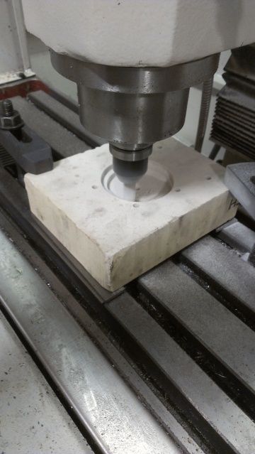
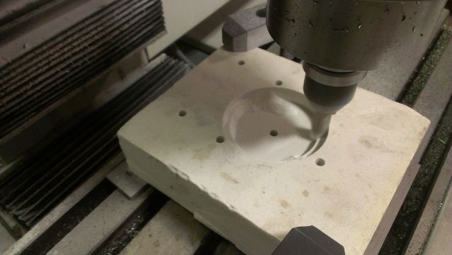
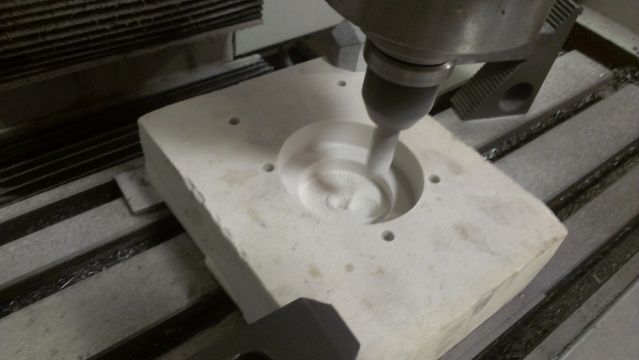
I have an engine half on our CNC mill and I have pulled all of the bolt holes locations as well as the crank center and the dowel centers out to half-thou from each other. Next plan is to carve this thing out of machinst foam and determine if I can put something together.
I don't have much in the way of pictures, but I will post them up when they come.
I spent a few nights knocking out a desing in Autocad Inventor and I think that I ahve all of the design kinks worked out... Prototype time!
I have an engine half on our CNC mill and I have pulled all of the bolt holes locations as well as the crank center and the dowel centers out to half-thou from each other. Next plan is to carve this thing out of machinst foam and determine if I can put something together.
I don't have much in the way of pictures, but I will post them up when they come.
-
DaylightDies
- Spree

- Posts: 161
- Joined: Mon Aug 24, 2009 10:18 am
- Location: Kadena ABS, Okinawa Prefecture, Japan

Re: Twin dio possible?
in taiwan , has done build 2 cylinder dio motor.. not new... 
-
Majourlittle
- Elite
- Posts: 314
- Joined: Thu Feb 24, 2011 11:09 am
- Location: Broken Arrow, OK
Re: Twin dio possible?
Im not doing this to be unique. I am atempting this for the * of it. I am also doing this on a cnc so that it can be rapidly replicated for others in the
I have an idea of changing the position of the intakes onto the front side of the motor. The theory is that it will pull a/f directly into the crank and will allow for a more compact design.
I have an idea of changing the position of the intakes onto the front side of the motor. The theory is that it will pull a/f directly into the crank and will allow for a more compact design.
Re: Twin dio possible?
Nice, mate the intakes to the center section. How do you plan on connecting the cranks together? A coupler of some sort Id assume. I use to have a RZ500 LC, here in the states known as a RD500 LC and the cranks were 2 separate parts, its was a V4 design with upper and lower sets of reeds and 4 upper and lower carbs. Really neat bike I had bought brand new and kept through my 20s. Scary fast for "only" a 500cc.
-
Majourlittle
- Elite
- Posts: 314
- Joined: Thu Feb 24, 2011 11:09 am
- Location: Broken Arrow, OK
Re: Twin dio possible?
A little photoporn
Inital idea inspired by input from those that have forgotten more than I know...
Measuring for the critical areas and cutting some foam.
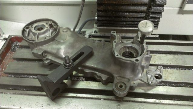
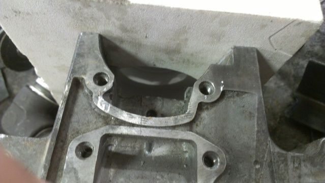
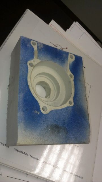
I have the location of all the mounting holes sorted. It all lines up like it should. I need to go through and sort out the way that it is machined out. I plan on splitting the inserted case in half and bolting it together in a four-piece sandwich. I will transfer this all back into autocad and work out the details as well as a machining mount.
Enjoy.
Inital idea inspired by input from those that have forgotten more than I know...
Measuring for the critical areas and cutting some foam.
I have the location of all the mounting holes sorted. It all lines up like it should. I need to go through and sort out the way that it is machined out. I plan on splitting the inserted case in half and bolting it together in a four-piece sandwich. I will transfer this all back into autocad and work out the details as well as a machining mount.
Enjoy.
Re: Twin dio possible?
hehe well when you are ready i got some 49mm nicalsil bores for that !|
once get that tested , i want to try some 52.6 cranks 54 bores!
once get that tested , i want to try some 52.6 cranks 54 bores!
-
Majourlittle
- Elite
- Posts: 314
- Joined: Thu Feb 24, 2011 11:09 am
- Location: Broken Arrow, OK
Re: Twin dio possible?
Well it appears that grainger has 175mm long M6 double ended studs for (reasonably) cheap. I think that I may machine this whole thing as one piece. Wonder what a chunk of billet will cost!
-
tazland001

- Board Supporter
- Posts: 1333
- Joined: Thu Apr 30, 2009 11:46 pm
Re: Twin dio possible?
wow that looks kewl. I understand what you are doing but could never do anything like that. What a neat tool you got there. I got a wrench. lol.
No but really hats off. Cant wait to see more. The question is whos gonna ride that thing pegged.
Taz
No but really hats off. Cant wait to see more. The question is whos gonna ride that thing pegged.
Taz
-
Majourlittle
- Elite
- Posts: 314
- Joined: Thu Feb 24, 2011 11:09 am
- Location: Broken Arrow, OK
Re: Twin dio possible?
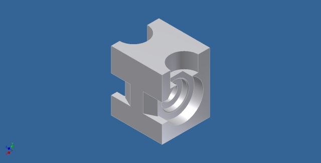
Alright, me and Mr. Graham bell sat down for a little brain-fart session and after banging my head against the wall for a few hours, this is what fell out.

Basically I will shave 8mm off of each case and then machine this SoB out of some 6061 and build me a motor. As you can see, the intake ports are on the front of the motor and feed directly into the crank... I sized the opening to be 10% of a 28mm carb opening. I think that is correct, but I need some input!
Input required!!!!
Progress will come as follows...
Stage one: Design
I will complete the design now and determine if this is suitable for building
Stage two: Tooling
I will collect the correct tooling and build this part out of foam as shown in the previous posts. This will allow me to work the kinks out.
Stage three: Save my pennies
You think that building a AF is expensive, try doing two, and add the cost of a chunk of AL.
Stage four: Magic
That's right, I cut it.
Stage five: Grow bigger balls