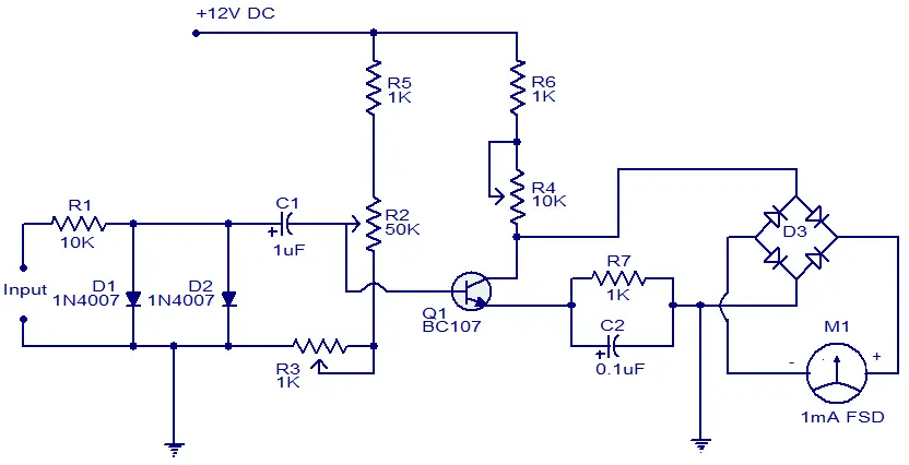
>> NG: MW: Here's a simple tach circuit. Frequency to Current conversion.
Thanks - these day's it's still amazing to see how IC's took over simple circuits. One thing about the converter shown, is there are 3 adjustment pots. Those cost more than anything but the meter, then they incur costs calibrating them.
While searching I ran into a 50 year old Corvair tach circuit. It's simple and adds regulation of the 12v input (VR1). I'd guess the Corvair circuit remains cheaper than KEGE design

, however, it likely needs some changes to use with our scooter pickups. Also KEGE likely spent a good deal of effort to make the design low cost - so take it as arm chair observations...
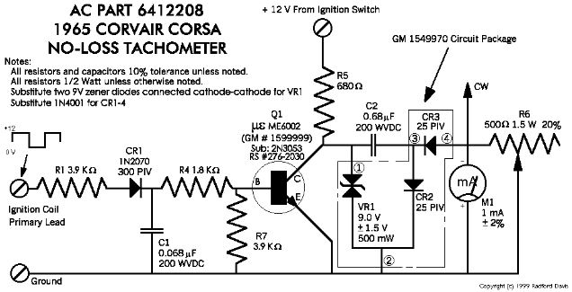
- Corvair_Tachometer.JPG (57.3 KiB) Viewed 7895 times
The circuit is easy to simplify and describe in non-tech terms
The pic below replaces input trigger circuitry. It represents that as a switch
There are only two states
- State 1: Charge ---> When switch is open,
Capacitor C2 is filled with a controlled 'bucket' of charge, where VR1 regulates how full, and the value of C2 is the bucket's capacity
- State 2: Measure ---> When switch is closed
"Bucket' C2 is emptied into the river of current.
At the designed full scale RPM ( we'll assume 8000 RPM), 8000 buckets/minute results in an average flow of 1mA, moving the meter to full scale
At intermediate RPM, the average flow is proportional to input RPM. Thus 4000 RPM = 0.5mA, 2000 RPM = 0.25 mA etc.
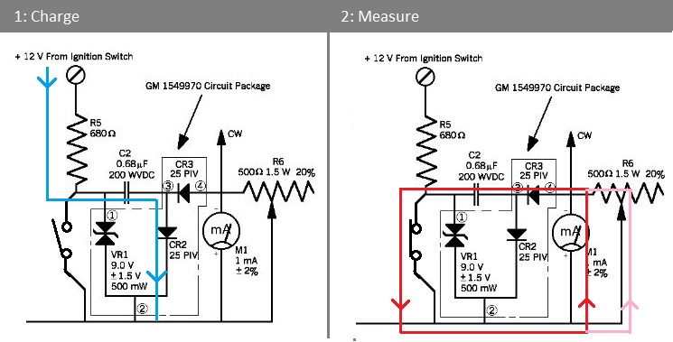
- Corvair_Tach_Measurement_Portion_of_Circuit.jpg (76.75 KiB) Viewed 7895 times